


 Google

TRIOL AT24 line RT
Hacer un pedido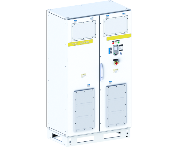
Beneficios distintivos
-20 ºC…+50 ºC
Operating temperature
IP55 (NEMA3R) / NEMA4/IP65
Enclosure
Removable graphic terminal
Induction supply or SRP controller
Built-in
Input circuit breaker, DC-link and braking IGBT- chopper
Remote control terminal
transient graphs
Sobre el producto
Complete cabinet solution for oil production
Variable Frequency Drive Triol AT24 line RT is a premium solution for submersible and surface oil production pumps (including SRP and PCP) with metal housing with the possibility to install additional options inside the cabinet. Triol AT24 VFD line RT is a complete cabinet for placing the main and additional functionality in one place and is a universal drive that controls both SRP and PCP, while it is also used for other types of industrial equipment, such as HVAC systems, fans, compressors, etc.
Special algorithm for PCP
Triol AT24 VFD line RT and line SR are identical in functionality, but line RT is more versatile due to special algorithm for PCP: implementation of kinetic buffering algorithm that allows the drive to remain in operation during short-term (up to 0.5 sec) power supply failure and “catch on fly” mode for induction motor with the turbine rotation output.
Two versatile versions
It is possible to optionally install input and output filters inside Triol AT24 VFD line RT cabinet. Triol AT24 VFD line RT is available in two versions: with a removable wireless control graphic terminal with induction supply or with an intelligent well controller with a 3” touch screen (optional – 7” touch screen).
Especificaciones
| Input | |
|---|---|
| Input voltage, V | 3х380 / 3х480/ 3×690 (-15 % …+10 %) |
| Input frequency, Hz | 50 / 60 (-5 %…+5 %) |
| Output | |
| Output current, A | 24 … 400 |
| Output frequency, Hz | 0.5…400 |
| Frequency resolution, Hz | 0.1 |
| Acceleration / deceleration time, s | 1 …4000 |
| Overcurrent characteristics | 150 % of rated value for 60 sec |
| Efficiency, % | >97 |
| Motor control | |
| Control methods | V/f (volts-per-hertz) (5 reference point) sensorless vector control (open-loop) sensor vector control (close-loop) |
| PWM frequency, kHz | 2…10 |
| Speed range | 1:100 in open-loop system 1:1000 in closed-loop system |
| Speed accuracy (static) | ±10% of motor nominal slip in open-loop system ±0.1 % of rated speed in close-loop system |
| Torque accuracy | ±10% in open-loop system ± 5 % in close-loop system |
| Braking | By frequency
Coasting Dynamic |
| Acceleration / deceleration types | S-curve, linear (3 reference points) |
| Interface | |
| Terminal | Options:
Removable graphic terminal with induction power / SRP controller with 3.5” or 7″ touchscreen |
| Light alarm | “Ready”; “Run”;” Fault”, “Control channel” |
| Push buttons | “Start”; “Stop”; “Program”, navigation keys |
| Control signals | |
| Customer supply | 10 V DC, up to 30 mA 24 V DC, up to 150 mA |
| Number of discrete inputs | 8 |
| Discrete inputs | programmable |
| Discrete inputs type | 24 V |
| Number of relay outputs | 4 |
| Relay outputs type | 250 V, 1 A |
| Number of analog inputs | 2, open collector |
| Analog inputs | Programmable 0…10 V / 0…5 mA / 4…20 mA |
| Number of analog outputs | 1 |
| Analog outputs | Programmable 0…10 V / 0…5 mA / 4…20 mA |
| Communication | |
| Physical Interface | 2 wire RS-485 for Modbus |
| Communication protocols | Modbus RTU |
| Frame transmission | 115200 bps by default 1200 -250000 bps |
| Data format | 8 bits, 1 stop bit, no parity |
| Number of addresses | 1…255 for Modbus |
| Access | Slave |
| Protection | |
| Supply protections | Phase loss, phase sequence fault |
| Motor protections | Overcurrent Overload Underload Phase loss Current unbalance Encoder open circuit Brake resistor open circuit |
| VFD protections | Overload, Overheating, DC-link undervoltage, DC-link overvoltage, Power switch failure |
| Protections provided SRP controller | Gearbox torque limit; Limiting the effects of gas; Limiting the minimum load on the bar; Limit the maximum load on the bar; Restriction of the minimum and maximum filling of the pump |
| Insulation | Galvanic isolation between power and user circuits |
| Insulation resistance | >1 MQ |
| Configuration | |
| Circuit breaker | Built-in |
| DC-link | Built-in |
| Braking IGBT- chopper | Built-in |
| Braking resistors | Built-in |
| Input EMC filter (C2) | Option, built-in |
| Input passive harmonic filter | Option, built-in |
| Construction | |
| Enclosure | IP54 (NEMA3R) |
| Cabinet material | Steel |
| Cooling | Forced air |
| Noise level, @ 1 m, dB(A) | <75 |
| Installation | Floor mounting |
| Maintenance | One-side |
| Cable entry | Bottom |
| Operating conditions | |
| Operating conditions | Outdoor |
| Operating temperature | -20…+50 °C (-4…+122 F) |
| Storage temperature | -40…+60 °C (-40…+140 F) |
| Relative humidity, % | from 5 to 90 non-condensing |
| Altitude, m | up to 1000 m – rated power above 1000 m – with reduced power |
Functions
- Start /stop/reverse of motor with set acceleration and deceleration rates
- Motor speed and torque control
- Auto-tuning of motor parameters (with rotation and without)
- PID-controller
- Automatic restart
- “Catch on the fly” mode
- Kinetic buffering
- Motor group control
- Operation by calendar
- Energy and electricity meters
- Encoders supported – incremental, absolute, sine/cosine
- Accelerated passing of resonant frequencies (3 ranges)
- Recording the last 32 reasons of failures